Equipment Identification Design Information
Identification
In order to track equipment lifecycle information, each piece of equipment to be
tracked must be permanently identified. Although this is a simple concept, there
seems to be a lot of confusion about equipment identification, instead of location
identification. The use of a stamped brass or steel tag riveted to the machine is
the preferred identification technique. Typically, these tags are readily available
and inexpensive. Complex ID strategies are discouraged, a 6-10 character alpha-numeric
ID is sufficient (Figure1). Sometimes a plant attempts to use equipment serial numbers
to identify equipment. Often a plant will find that serial numbers are not unique
and that identical equipment ordered at the same time may have the same serial number.
Also, serial numbers are complex with over 20 characters. A common problem in reading
serial numbers from a stamped nameplate is that S, Z, and 5 tend to look the same.
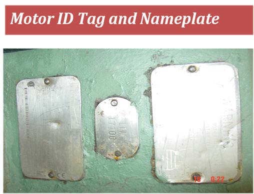 Figure 1
Design Information
Tango™ has predefined equipment design templates for hundreds of equipment types.
Figure 2 shows typical motor equipment types. These design templates have been developed
in cooperation with our users and may be modified or expanded to meet a user’s specific
need. Equipment design information is divided into required and non-required fields.
The required fields are typically the equipment ID (plant tag), nameplate information
and company stock number (figure 3,4, 5). Non-required fields define the equipment
data needed to assist in condition problem diagnosis, (like bearing IDS and number
of rotor bars or station slots), mechanical details, and sometimes installed accessories.
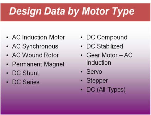 Figure 2
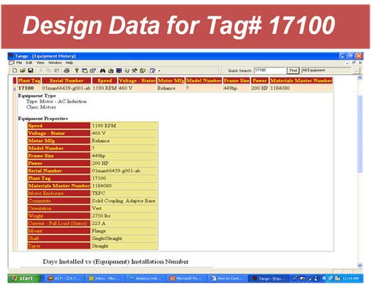 Figure 3
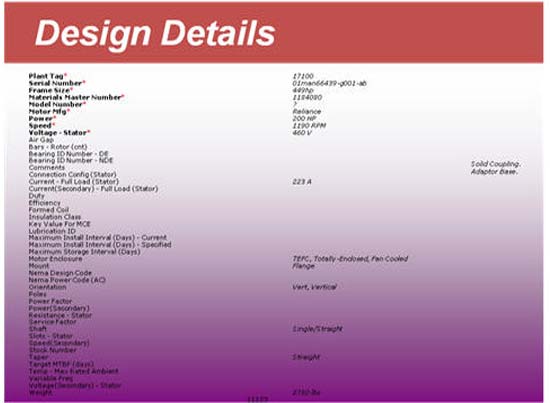 Figure 4
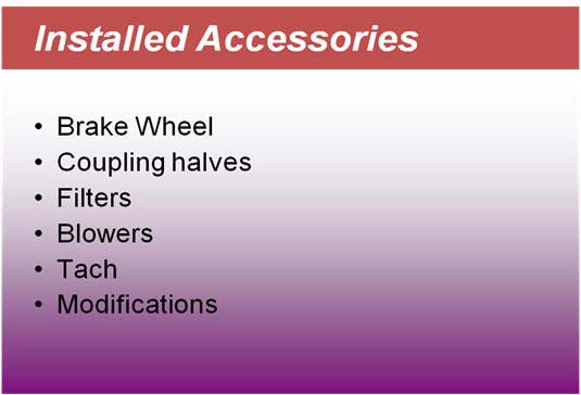 Figure 5
Search Functions
Searching for replacement equipment in spares with Tango™ is accomplished by selecting
an equipment type, then entering search criteria taken from the required fields
for the selected equipment type.
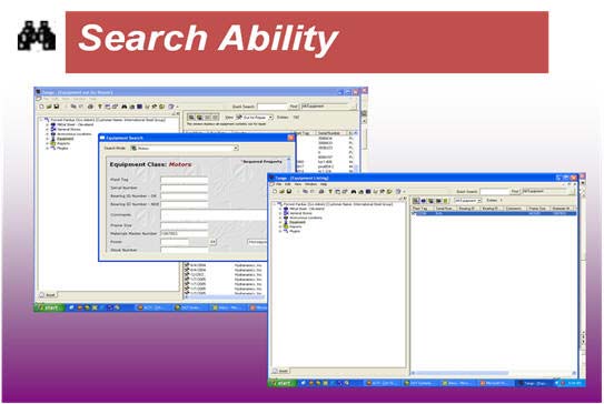 Figure 6
Design Documents
Associated with the design details of equipment, Tango™ allows the linking of design
documents. This may be as simple as a photo of the machine or items like manuals,
repair procedures lubrication specifications.
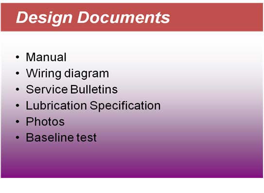 Figure 7